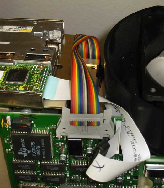
One day I turned on my TDS524A and got the dreaded tick tick tick of the power supply trying, and failing, to start. Long story short, pulled the IDC16 connector to the CRT section and everything worked (except for the CRT.) A VGA monitor connected to the rear VGA connector showed that the oscilloscope scope otherwise was fine. I pulled the CRT section and did not find any problems visually and tested a few components with no luck. Not having a schematic did not help.
As the CRT also had some of the LCD shutter index gel problems common
to this model I decided to explore replacing it with a LCD. I found a
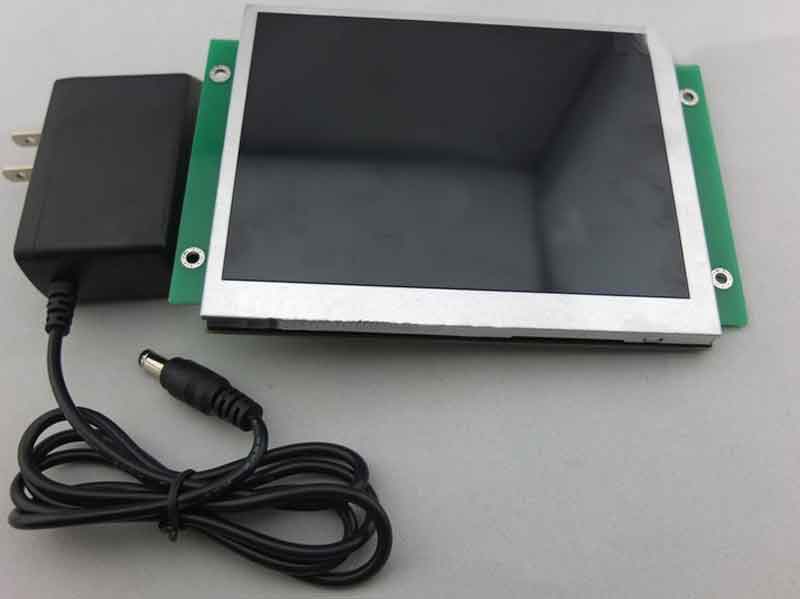
640 x 480 VGA LCD on eBay for $68.99 and decided to give that a try.
It is a bit smaller than the original CRT/LCD shutter at 5.6 inches, but not too small.
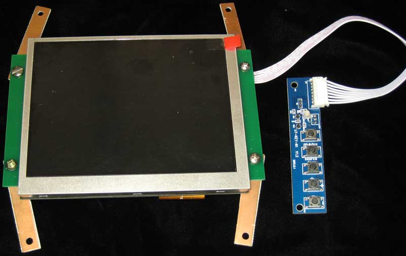
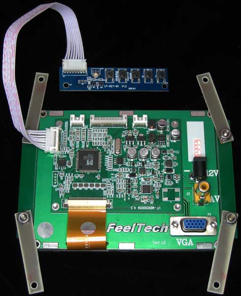
eBay TFT LCD $68.99. Got mine from seller 2012moon816.
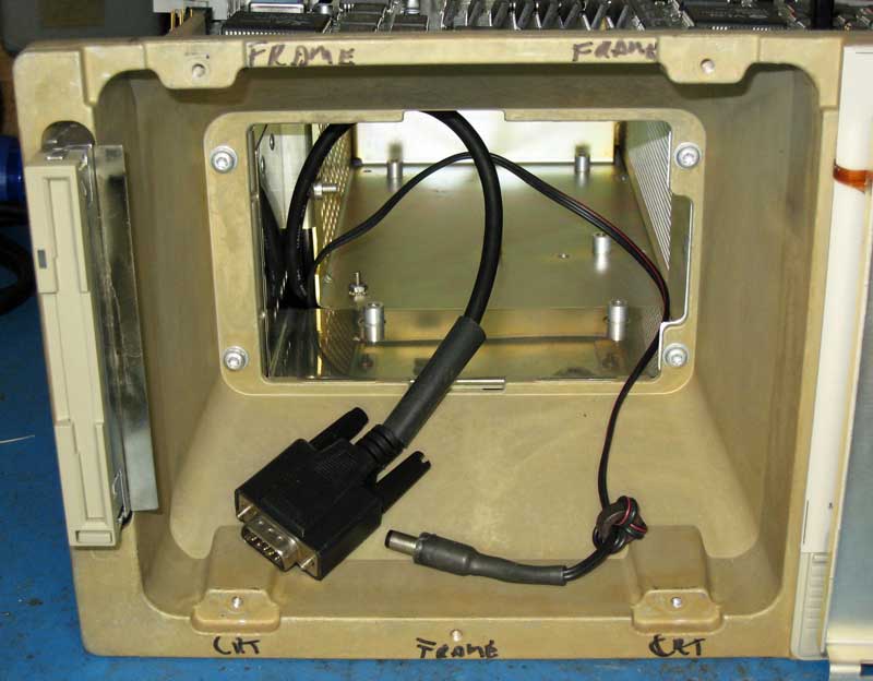
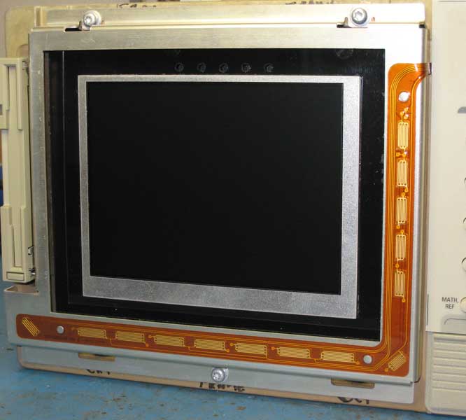
The CRT and its power supply were removed. A VGA cable and a power cable were run into the CRT cavity through existing holes. BTW, no holes needed to be drilled or the scope otherwise modified for this conversion.
CRT, LCD shutter, CRT power supply removed.
The LCD requires 12VDC at about 200 mA. I used the 24 V that would have powered the CRT circuitry. This is regulated down to 12V with a 7812. +24 V is on pins 1 & 2, return on 5,7, & 9, of the 16-pin header connector.
A LM7812 voltage regulator is added.
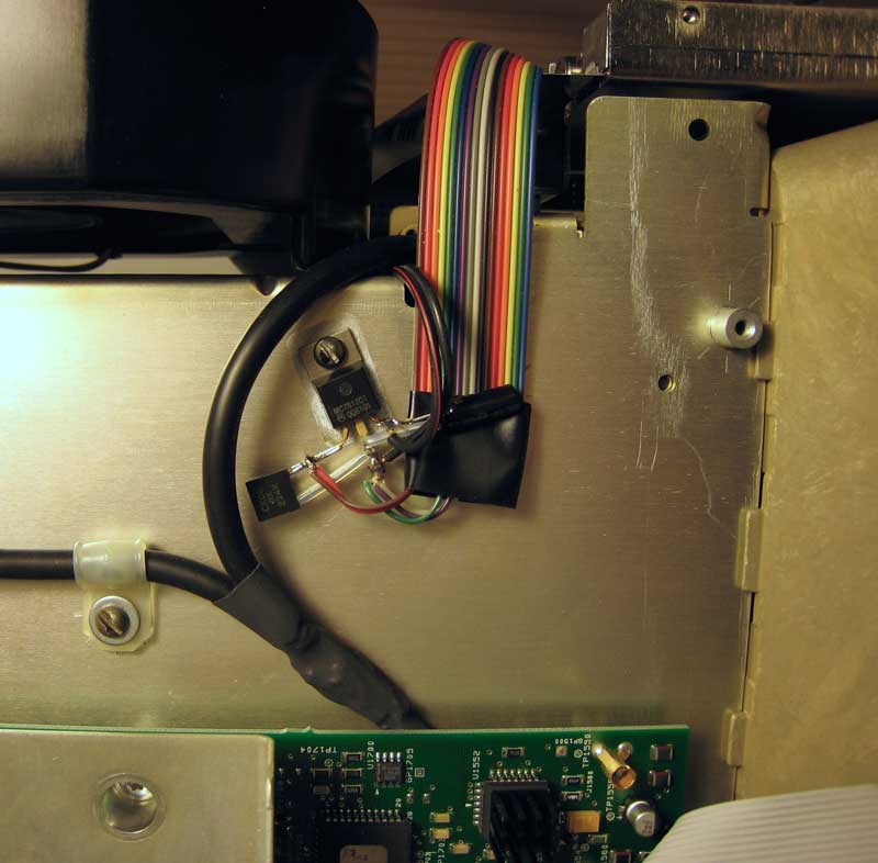
As the 24 V power was fused with a 2A fuse on the CRT board I figure it?s plenty safe to be pulling a couple hundred mA from that line.
Stealing the 24 VDC formerly used by the CRT.
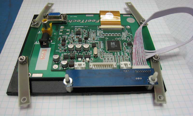
The LCD will be mounted using the existing four tapped holes used to hold the CRT. Four mounting straps were cut out of scrap PCB stock.
Mounting straps made from some bare PCB stock.
Mounting straps made from some bare PCB stock.
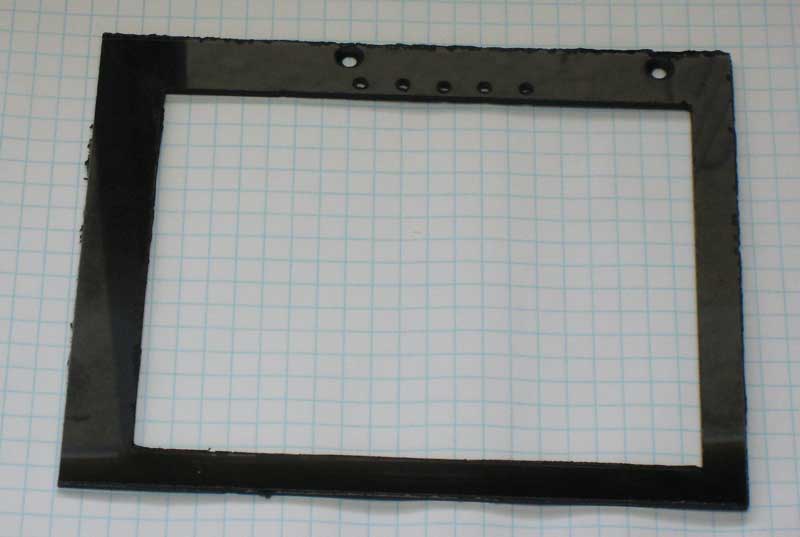
A frame was fashioned out of Lexan, mostly for cosmetics.
Lexan frame reverse painted black.
Once the LCD is set up the push button assembly does not seem to be needed, but just in case I included it in the mod.
Push button assembly is mounted on the Lexan frame.
Almost done.
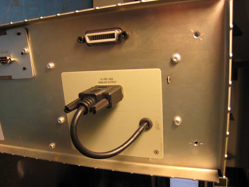
Okay, this part of the mod is not very sophisticated. The VGA cable is run through an existing hole (previously covered by a sticker) to the back of the oscilloscope and plugged into the VGA connector. This retains the ability to plug in a larger monitor. The VGA cable did have to be cut and spliced to be able to route it through existing holes.
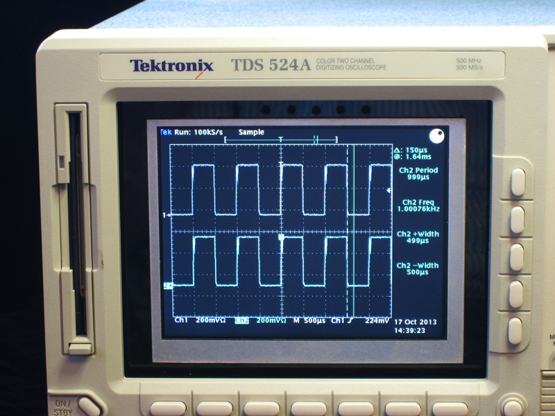
Hey, not that bad! Smaller than the original CRT, but same resolution and plenty useable.
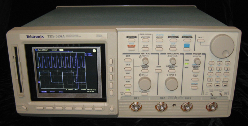
Ahhhh, back where she belongs. Happy, happy, happy.
Visit the largest used high-tech
electronic test and production equipment dealer directory on the net:
Used Electronic Test and Semiconductor Production Equipment Dealer Directory
Copyright © 2020. All rights reserved.